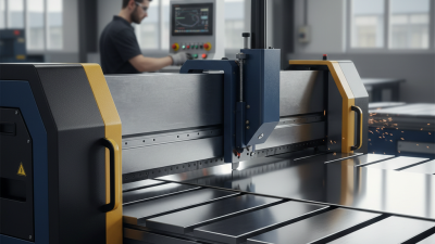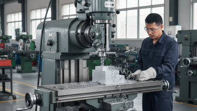
Choosing a Milling Drilling Machine is not simply a matter of comparing prices or motor power. The right decision depends on accuracy, material, workload, operator skill, and available workshop space. A machine that performs well on aluminum may struggle with hardened steel. A compact model may save floor space but sacrifice rigidity during deep drilling. These details matter when a workpiece must hold a tight hole position or a smooth milled edge.
W. Edwards Deming, a respected manufacturing quality expert, said, “Quality comes not from inspection, but from the improvement of the production process.” His principle applies directly to machine selection. A reliable Milling Drilling Machine should support consistent results before defects appear. This guide introduces seven practical tips, including spindle speed, table movement, column stiffness, tooling compatibility, safety features, maintenance access, and total operating cost. Look closely.
A clean catalog can hide important weaknesses. A powerful motor does not guarantee precision. A low price can become expensive after repeated repairs, vibration, or unsuitable tooling. The best choice may not be the largest machine. It should match the work honestly, even when that means admitting your original plan was unrealistic. Check real samples, inspect controls, and ask suppliers for measurable accuracy data. These steps cannot remove every uncertainty, but they can reduce costly surprises and support a more dependable buying decision.
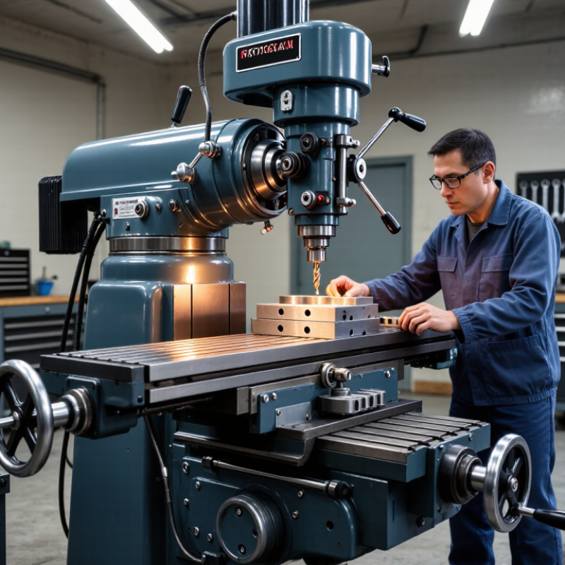
Tip 1: Identify the materials you will machine. Steel, cast iron, aluminum, and composites require different cutting speeds, tooling, and rigidity. A machine suitable for aluminum may struggle with hardened steel.
Tip 2: Measure your largest workpiece, including its length, width, height, and clamping space. Leave clearance around the spindle and table. Tip 3: Calculate the real load, not just the product weight. Typical jobs may weigh 500–2,000 kg, especially with fixtures and unfinished castings. Confirm the table’s rated capacity and support points.
Tip 4: Check the table size and travel range against your daily work. A large table is useful, but excessive capacity can increase cost and floor space. Tip 5: Examine spindle power and torque for the materials you cut most often. Tip 6: Review the machine’s rigidity, column structure, and guideway design. Vibration can leave visible marks on a steel surface. Tip 7: Confirm loading access, lifting height, and floor requirements before ordering. A machine can meet every specification and still be difficult to install.
In practice, I would record three sample jobs before comparing machines. Include material grade, dimensions, fixture weight, cutting depth, and production frequency. This creates reliable evidence instead of relying on sales estimates. Be careful with “maximum capacity” figures; they may describe ideal conditions, not continuous operation. I have seen teams overlook chip clearance and coolant access. That mistake later slowed setup and cleaning. Ask for test-cut data when possible, and document the results for future decisions.
7 Tips for Choosing a Milling Drilling Machine
Compare 3,000–12,000 rpm Spindles Using Torque, Power, and Material Data
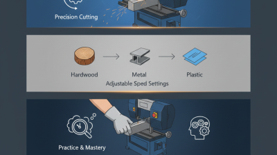
A 3,000 rpm spindle suits large cutters and tough steel. It delivers stronger low-speed torque. A 12,000 rpm spindle favors small tools, aluminum, plastics, and faster surface speeds. Do not judge performance by rpm alone. Check the torque curve across the working range. Peak torque figures can mislead.
Match spindle power with cutting demands. For steel, prioritize rigidity, steady torque, and controlled heat. For aluminum, higher speed can improve finish, but chip removal becomes critical. Stainless steel needs moderate speed, sharp tooling, and consistent feed pressure. Titanium demands even more caution. Heat builds quickly.
Measure the cutter diameter, material hardness, depth of cut, and expected feed rate. Then compare continuous power, not only short-term peak power. Confirm the machine’s taper, bearing design, cooling method, and table stiffness. A powerful spindle on a flexible frame still produces vibration. Listen for chatter. Inspect the cut surface.
I once selected a faster spindle for small aluminum parts. The finish improved, but the machine struggled with larger steel tools. That choice looked efficient on paper. It was not. Test cuts revealed the missing detail: low-speed torque. Record sound, temperature, tool wear, and dimensional accuracy. Leave room for imperfect data. Real workshop conditions rarely match catalog charts.
Compare 3,000–12,000 rpm spindles using torque, power, and material data
This comparison uses a constant 2.2 kW spindle power rating. Torque is calculated as T = 9550 × P ÷ n, where torque is in newton-metres, power is in kilowatts, and spindle speed is in revolutions per minute. Cutting speed is calculated for a 10 mm cutter using V = π × D × n ÷ 1000. Lower speeds provide more torque for steel and stainless steel, while higher speeds can be useful for aluminium when tooling, rigidity, cooling, and chip evacuation are appropriate.
7 Tips for Choosing a Milling Drilling Machine
Evaluate 3-, 4-, and 5-Axis Configurations Against ±0.02 mm Accuracy Targets
Start with the part, not the axis count. A rigid 3-axis machine can hold ±0.02 mm on simple plates when alignment is controlled. Check spindle runout, table flatness, and backlash before trusting specifications. A fourth axis helps with indexed faces, but every rotary joint adds setup error. Measure the rotary center after installation.
Choose 5-axis capability for curved surfaces, short tools, and fewer re-clamping operations. Do not assume five axes guarantee tighter results. Thermal growth, tool deflection, and pivot-point errors can exceed the target. Ask for volumetric accuracy data, not only linear positioning figures. Verify it with a calibrated ball bar or laser system.
Inspect probing repeatability, controller compensation, and service records. Run a test cut in your actual material, then measure several features at room temperature. Keep cutting forces stable. I once blamed the machine for a 0.03 mm error, but the fixture had shifted slightly. That mistake changed my inspection routine. Leave room for skill, maintenance, and imperfect assumptions. Calibration matters.
In practical machine acceptance, verify ISO 230-2 positioning tests before trusting brochure accuracy. Check whether the supplier reports unidirectional accuracy, bidirectional accuracy, repeatability, and reversal error. These figures reveal backlash more clearly than a single “accuracy” number. Ask for the test temperature, axis travel, feed rate, probe type, and calibration date. Missing details matter.
Use a laser interferometer report when possible. Confirm that the machine completed repeated approaches from both directions. ISO 230-2 testing commonly uses repeated measurements across several positions. Compare the measured results with your smallest expected tolerance. Inspect rigidity, too. Check column deflection, table support, spindle bearing preload, and guideway behavior under cutting load. A dial indicator can expose movement during a controlled side-load test. It is simple. It is not perfect.
The World Robotics 2024 report recorded 541,302 industrial robot installations worldwide in 2023. That growth increases demand for predictable machining, especially in automated cells. However, automation data does not prove milling accuracy. Do not confuse market momentum with machine capability.
Run a circular interpolation test, a stepped-depth cut, and a repeatability test after warm-up. Listen for chatter. Measure the finished features, not only the machine screen. Also inspect backlash compensation settings, because software can hide mechanical wear temporarily. A machine may pass acceptance yet drift later. That uncomfortable possibility deserves a maintenance plan and documented retesting.
Tip 1: Match the spindle taper to your cutting work. BT30 suits lighter milling and compact parts, while BT40 offers greater rigidity for deeper cuts. Check gauge length, pull-stud standards, and local tool availability.
Tip 2: Inspect tool-changer capacity carefully. A 10-tool changer may handle simple jobs, but 24 positions reduce setup interruptions. More pockets are not always better. Extra capacity adds cost and maintenance points.
Tip 3: Test the control interface before purchase. Operators should find offsets, tool tables, and alarm history quickly. Deloitte’s smart-manufacturing survey reported that 86% of manufacturing leaders expect smart operations to drive competitiveness within five years. Usable controls matter.
Tip 4: Confirm data connectivity, backups, and cybersecurity options. Ask whether programs transfer through approved network methods and whether access permissions can be managed. A modern control can still create friction.
Tip 5: Compare spindle speed, torque, and acceleration with real materials. A high-speed rating means little if torque drops during heavy cutting.
Tip 6: Request a service-response policy in writing. Clarify spare-parts access, remote diagnostics, technician coverage, and training. The 2024 World Manufacturing Forum report emphasizes skills and digital readiness as persistent manufacturing challenges.
Tip 7: Calculate ownership cost beyond the machine price. Include tooling, coolant, calibration, electricity, software, and downtime. I would leave room for error in the forecast; production rarely follows the brochure perfectly. Ask for a sample cycle test using your own part, tools, and tolerance requirements.